


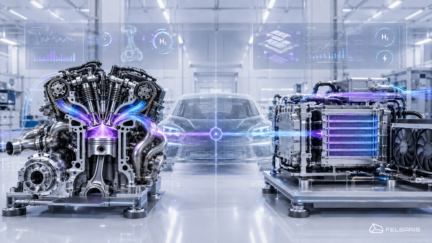
A hydrogen internal combustion engine and a fuel-cell powertrain use the same energy carrier, yet they present engineers with fundamentally different challenges. In a hydrogen internal combustion engine, or H₂ICE, mixture formation, ignition, boosting, nitrogen oxide emissions and exhaust aftertreatment shape the technical concept. In a fuel-cell system, the main areas of focus are air supply, water management, cooling, hydrogen quality, electrical integration and ageing.
The appropriate technology depends on the specific duty cycle, the required continuous and peak power, available packaging space, hydrogen supply and existing development and manufacturing capabilities. Maintenance, payload, start-up behaviour and thermal boundary conditions also form part of the comparison.
A single peak-efficiency figure or an isolated component metric is therefore rarely sufficient for selecting a technology. The relevant level of comparison is the complete system, from the hydrogen tank to mechanical power at the wheel, shaft or working implement.
Hydrogen engines and fuel cells convert hydrogen in different ways
In a hydrogen engine, combustion converts the chemical energy of hydrogen into pressure work. The pistons, connecting rods and crankshaft turn this into mechanical power. In a fuel-cell powertrain, a stack converts hydrogen electrochemically into direct current. Power electronics and an electric machine then provide the mechanical drive power.
These conversion principles lead to different system architectures:
| System area | H₂ internal combustion engine | Fuel-cell powertrain |
| Energy converter | Internal combustion engine | Fuel-cell stack |
| Power output | Mechanical via crankshaft | Electrical via power electronics and electric machine |
| Air system | Intake system, boosting, optional EGR | Air filter, compressor, pressure control, optional humidification |
| Hydrogen system | Pressure control and injection | Pressure control, anode supply and optional recirculation |
| Emissions system | Exhaust routing and concept-dependent aftertreatment | Exhaust-air and water management |
| Thermal management | Engine, oil, charge air, exhaust system and optional hybrid components | Stack, compressor, battery, electric machine and power electronics |
| Transient support | Optional hybrid powertrain | Typically a buffer battery in mobile systems |
| Power transmission | Transmission or hybrid powertrain | Electric powertrain |
A complete fuel-cell architecture therefore comprises considerably more than the stack. The US Department of Energy lists components such as air compressors, fuel processing, power conditioning and humidification as typical elements of a fuel-cell system. In vehicles, an electric machine, battery, DC/DC converter and dedicated thermal management system are also required. (The Department of Energy’s Energy.gov)
How a hydrogen internal combustion engine works
H₂ICE stands for hydrogen internal combustion engine. Hydrogen enters the engine through port fuel injection or direct injection and is ignited by an ignition source.
The basic mechanical architecture resembles that of a conventional internal combustion engine. The fuel system, mixture formation and combustion strategy must, however, be adapted to the properties of hydrogen. Relevant factors include:
- Injection pressure and injection timing
- Injector position and design
- Displacement of intake air by gaseous hydrogen
- Local hydrogen concentration in the combustion chamber
- Ignition timing and ignition energy
- Boosting and exhaust back pressure
- Air-fuel equivalence ratio, lambda
- Exhaust gas recirculation, or EGR
- Backfire and pre-ignition
- Combustion-chamber and component temperatures
- NOx formation and exhaust aftertreatment
Existing engine platforms can provide a technical basis. Conversion still requires the hydrogen, combustion, air and cooling systems to be designed and validated specifically for the new application.
How a fuel-cell powertrain works
Polymer electrolyte membrane fuel cells, or PEM fuel cells, are often considered for mobile applications. At the anode, hydrogen is separated into protons and electrons. The electrons flow through an external circuit. At the cathode, protons, electrons and oxygen react to form water, producing electrical energy and heat.
A vehicle-ready or machine-ready system also requires:
- Air supply with filter and compressor
- Hydrogen supply and pressure control
- Humidity and water-management control
- Stack cooling
- Power electronics
- Buffer battery
- Electric traction motor
- Control, diagnostic and protection functions
The battery can absorb braking energy, provide additional power for short periods and smooth the load on the stack. The sizing of the stack and battery therefore affects both transient response and the operating-point distribution of the fuel-cell system. (Alternative Fuels Data Center)
The technical comparison starts with the duty cycle
Rated power describes only one design point. Time-dependent loads provide a much more meaningful basis for the technology decision.
A suitable duty cycle includes, among other factors:
- Mechanical or electrical power over time
- Rotational speed and torque
- Vehicle speed
- Duration of high-load periods
- Frequency and rate of load changes
- Periods of idling and standstill
- Start-up and shutdown events
- Regenerative braking potential
- Ambient temperature and elevation profile
- Additional consumers such as hydraulics, climate control or power take-offs
A long-haul truck, a city bus and a construction machine can have the same rated power. Their requirements for continuous power, cooling, storage capacity, transient response and infrastructure can still differ substantially.
Continuous power and steady operating points
Extended high-load periods determine the thermal design of both concepts.
For H₂ICE, continuous operation increases the demands on areas including:
- Combustion-chamber and cylinder-head cooling
- Charge-air cooling
- Turbocharger and exhaust system
- Lubricating-oil circuit
- NOx control strategy
- Protection functions for component temperatures
In a fuel-cell system, stack temperature, air supply, coolant flow rate, compressor power and water management must remain stable throughout each operating condition. The electric machine, battery and power electronics also contribute to the total system heat load.
For both systems, thermal time histories are therefore more informative than considering maximum cooling capacity alone.
Dynamic load changes and peak power
Rapid load changes affect the sizing of both the energy converter and the energy storage system.
An H₂ICE can respond to load changes through throttling, injection, ignition, boosting and, where applicable, hybridisation. Turbocharger dynamics and thermal protection limits can restrict torque delivery.
In a fuel-cell powertrain, the battery often supports brief power peaks. This allows the stack to operate within a more deliberately selected range. The design must consider stack power, battery power, battery capacity, energy recovery and operating strategy together.
The relevant question is therefore the power delivery of the complete powertrain, rather than the response time of the energy converter in isolation.
Start-up, cold start and operating pauses
Start-up events require a separate set of requirements.
For H₂ICE, relevant factors include lubrication, mixture formation, ignitability, component temperatures and catalyst condition. In a fuel-cell system, water distribution, possible condensation, stack temperature and the energy required for start-up must also be considered.
The US Department of Energy treats cold start, start-up energy, and start and stop durability as separate technical targets for transport fuel-cell systems. This indicates that start-up behaviour and continuous operation present different development tasks. (The Department of Energy’s Energy.gov)
H₂ICE: mixture formation, combustion and NOx define the development window
Across the relevant engine map, a hydrogen engine must reconcile power, combustion stability, resistance to backfire, thermal loading and nitrogen oxide emissions.
Hydrogen has high diffusivity, wide flammability limits, low required ignition energy and rapid flame propagation. These properties provide considerable freedom in combustion design, while increasing sensitivity to local hot spots, unintended pre-ignition and backfire.
Port fuel injection or direct injection
The choice between H₂-PFI and H₂-DI affects air filling, mixture formation, packaging and validation effort.
H₂-PFI introduces hydrogen into the intake port or intake manifold. H₂-DI injects hydrogen directly into the combustion chamber.
| Criterion | H₂-PFI | H₂-DI |
| Mixture formation | Predominantly premixed | Strongly influenced by jet, timing and in-cylinder flow |
| Air displacement | Relevant because of gaseous hydrogen | Lower, as hydrogen enters the cylinder later |
| Backfire | Requires particular attention in the intake path | Intake-side risk can be reduced |
| Fuel system | Tends to require lower injection pressure | Higher demands on pressure supply and injector dynamics |
| Control variables | Injection timing, distribution and valve overlap | Injection pressure, start and end of injection, and ignition timing |
| CFD focus | Intake system, cylinder distribution and backfire | Jet penetration, local mixing and wall interaction |
| Validation requirements | Pressure trace, lambda, distribution and backfire events | Also requires robust injector maps and jet data |
The table provides qualitative guidance. The appropriate injection strategy depends on power, engine-speed range, combustion-chamber design, boosting, available pressure level and packaging.
In hydrogen-engine development, these variables must be assessed as an interconnected system.
Lean operation, EGR and water injection
Lean operation can influence combustion temperature and therefore NOx formation. As excess air increases, ignition stability, combustion duration, boost demand and achievable load also change.
EGR dilutes the cylinder charge with exhaust gas. This reduces oxygen concentration and local combustion temperature, while also affecting combustion duration and the stability limit.
Water injection can also be used to manage temperature. Additional components, water supply, control and freeze protection increase overall system complexity.
For all three approaches, the appropriate combination must be calibrated across the relevant engine map. Individual operating points do not provide a robust assessment of the complete system.
Nitrogen oxides and exhaust aftertreatment
When pure hydrogen is burned, the fuel itself produces no CO₂ because hydrogen contains no carbon. Nitrogen oxides can form as a result of high local temperatures and reactions between nitrogen and oxygen in the air. The US Department of Energy explicitly notes the potential for NOx formation during hydrogen combustion. (The Department of Energy’s Energy.gov)
Development must distinguish between two levels:
- Engine-out emissions: emissions measured directly downstream of the engine
- Tailpipe emissions: emissions after exhaust aftertreatment
The aftertreatment system requires suitable exhaust temperatures and an appropriate exhaust-gas composition. Lean operation creates different requirements from a stoichiometric concept. Load changes, cold start and ageing further affect the available operating window.
Fuel cells: air, water, temperature and ageing constrain the operating range
Fuel cells are often considered in terms of the stack alone. In a real vehicle or machine, the interaction between the stack and its auxiliaries is what determines system behaviour.
A fuel-cell system must control the following variables simultaneously:
- Hydrogen mass flow rate and anode pressure
- Air mass flow rate and cathode pressure
- Humidity
- Temperature
- Coolant flow rate
- Electrical load
- Battery state of charge
- Pressure differentials within the stack
- Start-up and shutdown events
Air supply and auxiliaries
The air compressor supplies oxygen to the cathode. Its compressor map, pressure losses and control strategy influence both available stack power and the system’s electrical parasitic load.
The air path can include a filter, compressor, heat exchanger, humidifier, pipework and exhaust-air path. These components interact:
- Higher pressure can alter the reaction conditions within the stack.
- Pressure losses increase compressor demand.
- The compressor heats the air.
- Temperature and pressure influence the humidity state.
- Load steps require coordinated control of the air and hydrogen paths.
The US Department of Energy identifies air compressors and humidifiers as central components of many PEM fuel-cell systems. The membrane requires an appropriate humidity level to function correctly. (The Department of Energy’s Energy.gov)
Water management and temperature control
Water management has two critical extremes. A membrane that is too dry has impaired proton conductivity. Excess liquid water can block pores and flow paths, impeding oxygen transport to the reaction zone.
Experimental and numerical studies show that condensation in porous layers can affect oxygen transport and fuel-cell performance. Local water distribution is therefore a spatial flow and transport problem. (OSTI)
Water management, temperature and pressure are closely coupled. Changes in operating point affect:
- Reaction heat
- Water production
- Evaporation and condensation
- Cooling demand
- Gas density and pressure loss
- Membrane humidity
A control strategy based on individual mean values can overlook local undersupply or liquid-water accumulation. Spatially resolved analysis may therefore be required for critical manifold, cooling and flow questions.
Ageing, load changes and operating strategy
The service life of a fuel-cell system depends on materials, operating strategy and the lifetime load spectrum. Start-stop events, temperature and humidity cycles, and changes in electrical potential can activate different ageing mechanisms.
The operating strategy therefore determines the regions in which the stack operates and how often critical transitions occur. A buffer battery can meet rapid power demands and smooth stack loading. It also adds mass, packaging requirements and control complexity.
NREL therefore evaluates fuel-cell vehicles using real-world driving data, stack operating hours, voltage degradation and operating behaviour. Durability is an application-specific system property, rather than a universal characteristic of the stack. (Research centre)
Thermal management shapes both system architectures
Both H₂ICE and fuel-cell systems require thermal management matched to the duty cycle. Their heat sources and permissible temperature levels differ.
In an H₂ICE, relevant heat flows arise in areas including:
- Combustion chamber and cylinder head
- Exhaust system
- Turbocharger
- Charge air
- Engine oil
- Coolant
- Where applicable, battery, electric machine and power electronics
For a fuel-cell powertrain, components to consider include:
- Stack
- Air compressor
- DC/DC converter
- Battery
- Electric machine
- Power electronics
Low temperature levels can require large heat-exchanger areas
The transferable heat rate depends on heat transfer, available area and the temperature difference to ambient. As the usable temperature difference decreases, heat-exchanger area, air mass flow rate or heat-transfer performance often needs to increase.
This does not support a general conclusion about which concept requires the larger radiator. Relevant factors include:
- Heat load
- Permissible coolant temperature
- Ambient temperature
- Radiator airflow
- Vehicle speed
- Fan power
- Packaging
- Fouling condition
- Operating duration
Applications combining high load with low vehicle speed are particularly demanding, including working machines, construction vehicles and special-purpose vehicles operating while stationary. In these cases, little natural cooling-air mass flow is available.
Cooling circuits must be derived from time histories
A cooling system should cover operating conditions including:
- Hill climbing or high tractive load
- Extended operation at low speed
- High ambient temperature
- Repeated acceleration
- Idling or stationary power take-off operation
- Cold start
- Rapid load reduction
- Heat soak after shutdown
A 1D thermofluid model can represent the circuits and heat flows over the duty cycle. 3D CFD complements this with local analysis of coolant distribution, heat-exchanger airflow, pressure losses and hot spots.
Packaging, mass and infrastructure belong in the system comparison
Comparing individual energy converters does not provide a robust assessment of the complete vehicle.
For H₂ICE, system mass includes the engine, boosting system, exhaust system, aftertreatment, transmission, cooling system, hydrogen supply and tank.
A fuel-cell powertrain combines the stack, air compressor, electric machine, power electronics, buffer battery, cooling circuits, hydrogen path and tank.
The assessment should cover:
- Total mass
- Payload
- Packaging space
- Centre of gravity
- Line lengths
- Protection and crash zones
- Radiator area
- Service access
- Mechanical and electrical interfaces
- Scalability within a vehicle platform
Hydrogen storage and refuelling
The storage and infrastructure concept affects both technologies. Relevant questions include:
- Is gaseous or cryogenic hydrogen being considered?
- How much energy must be stored for each shift or journey?
- How often can the system be refuelled?
- Will hydrogen be supplied at a depot or through a public network?
- Which pressure and temperature states occur during filling?
- What are the requirements for leak detection and venting?
- What periods of downtime are acceptable?
Predictable fleet routes and depot operation create different boundary conditions from freely deployed vehicles or machines.
Hydrogen quality must be specified for the application
Contaminants can affect components and energy converters in different ways. In fuel cells, contaminants binding to catalyst surfaces can impair performance and service life. Hydrogen quality must therefore be defined together with the fuel path and energy converter. (The Department of Energy’s Energy.gov)
ISO 14687:2025 specifies minimum quality characteristics for hydrogen in different mobile and stationary applications. The storage concept, supply chain and required treatment must suit the application. (ISO)
Maintenance, service life and existing capabilities affect project risk
An H₂ICE contains moving and lubricated components. Maintenance and durability considerations include:
- Cranktrain and valvetrain
- Lubricant
- Ignition system
- Hydrogen injectors
- Turbocharger
- Exhaust aftertreatment
- Pumps, valves and sensors
For the fuel cell, the focus shifts to:
- Stack degradation
- Air compressor
- Pumps and valves
- Cooling and humidity management
- Hydrogen path
- Power electronics
- Battery
- Electrical insulation and diagnostics
Existing development, manufacturing and service capabilities can have a major influence on implementation. A manufacturer with engine production, test benches and an established service network starts from a different position than a company with an electric powertrain platform and high-voltage expertise.
An economic assessment must therefore consider development effort, production conversion, spare parts, diagnostics, maintenance and the consequences of failure together.
Which technology suits which application?
The following matrix provides preliminary technical guidance. It does not replace a project-specific system analysis.
| Application criterion | H₂ICE as a candidate | Fuel cell as a candidate | Key project question |
| Existing engine platform | Existing mechanical systems and manufacturing may be reusable | Greater change to the powertrain architecture | Which assemblies and processes can actually be retained? |
| Existing electric powertrain | Hybrid integration required | Direct integration into the electrical architecture may be possible | How should the stack, battery and electric machine be sized? |
| High transient loads | Design combustion, boosting and, where applicable, hybridisation | Design the battery and air-path dynamics | How much power is required, and for how long? |
| Extended high-load periods | Assess combustion chamber, exhaust, NOx and cooling | Assess stack operation, compressor and heat rejection | What continuous power is required under real conditions? |
| High load at low speed | Fan and radiator airflow are critical | High thermal design demands may also arise | How will heat be rejected without sufficient ram air? |
| Existing engine service network | Potentially compatible with existing structures | New electrical and stack-related capabilities required | What maintenance structure is available? |
| Strict local air-quality requirements | NOx and aftertreatment are central | No combustion-related NOx emissions at the stack | Which system boundary and auxiliaries are included? |
| Depot or fleet operation | Predictable hydrogen supply | Predictable hydrogen supply | What refuelling and downtime windows are available? |
| High operating hours | Mechanical wear and maintenance | Stack degradation and auxiliaries | What real lifetime load spectrum applies? |
Long-haul commercial vehicles
For long-haul operation, daily mileage, payload, tank volume, gradients, motorway share, continuous power and refuelling windows are key factors. Radiator airflow and the service network also belong in the assessment.
These factors do not support a universal allocation to H₂ICE or fuel cells. Differences in route profile alone can substantially shift system sizing.
Construction, agricultural and special-purpose vehicles
These applications often combine high loads with low speed. Dust, contamination, long periods at idle, hydraulic consumers and mechanical power take-offs increase the demands on integration and cooling.
An existing mechanical powertrain architecture can favour H₂ICE. An already electrified working machine may offer a stronger starting point for a fuel-cell system. The assessment must represent the complete working cycle, including auxiliary consumers.
Buses and fleet vehicles
Defined routes and depot infrastructure simplify planning of the hydrogen supply. Frequent starts, regenerative braking, cabin heating, shift operation and availability requirements influence the powertrain architecture.
For a fuel-cell system, matching the stack and battery is particularly important. For H₂ICE, dynamic operation, exhaust temperature, NOx and hybridisation are central considerations.
Stationary generating sets and emergency power
Stationary systems require assessment of start readiness, load steps, continuous operation, fuel storage, useful heat recovery, maintenance access and redundancy.
An H₂ICE can use mechanical generator architectures and existing service concepts. A fuel cell provides a directly electrical energy converter. The appropriate solution depends on factors including operating hours, start-up requirements, waste-heat utilisation and hydrogen quality.
Simulation supports a robust preliminary technical selection
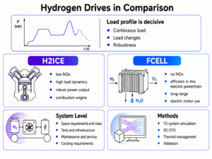
System variants can be compared under consistent boundary conditions before hardware is built. The choice of model class should follow the engineering question.
A typical workflow comprises:
- Define the application and system boundary
- Prepare the duty cycle
- Build a 0D or 1D system model
- Represent the energy converter, tank, auxiliaries and cooling circuits
- Compare operating strategies and variants
- Investigate critical local areas using 3D CFD
- Correlate models with measurement and test-bench data
- Document the validity range and uncertainties
1D system simulation for the duty cycle and overall architecture
For H₂ICE, a 1D model can connect the air path, boosting system, gas exchange, combustion, lambda, EGR, cooling circuits and vehicle load.
For a fuel-cell architecture, the system calculation can include the stack map, air compressor, hydrogen path, battery, electric machine, power electronics and cooling system, subject to the available data.
Typical results include:
- Operating-point distribution
- Hydrogen demand over the cycle
- Mass flow rates and pressures
- Auxiliary power demand
- Temperature histories
- Coolant states
- Battery state of charge
- Continuous and peak power
- Critical transients
1D system simulation and 3D CFD serve different purposes. The system model reveals interactions over the duty cycle, while the 3D analysis explains local causes.
3D CFD for local flow and heat-transfer questions
For H₂ICE, 3D CFD is suitable for investigating areas including:
- Hydrogen jets and mixture formation
- Intake-port and combustion-chamber flow
- Local hydrogen concentration
- Wall heat transfer
- Combustion-chamber hot spots
- Coolant-jacket flow
- Exhaust and radiator airflow
In fuel-cell systems, thermofluid questions can be investigated, for example:
- Air distribution
- Pressure losses
- Manifold flow
- Cooling-channel distribution
- Heat exchangers
- Condensate transport
- Radiator airflow
- Thermal integration of auxiliaries
Within Felsaris Engineering, system simulation, 3D CFD, and flow and heat-transfer analysis can be combined into a staged modelling chain.
Validation using test-bench and field data
Appropriate measurement data make simulation results more robust. For H₂ICE, relevant data include cylinder pressure, combustion profile, lambda, emissions, temperatures, pressures, mass flow rates and injector maps.
For fuel-cell systems, relevant quantities can include stack current, stack voltage, cell-voltage distribution, gas and coolant states, compressor power, electrical load and thermal measurements.
A robust validation strategy considers:
- Measurement uncertainty
- Sensor position
- Temporal resolution
- Steady-state and transient operating points
- Separate calibration and validation data
- Documented model limits
- Controlled extrapolation
Simulation can make variants comparable and identify critical operating conditions before hardware is built. Technical release still requires application-specific correlation with real-world behaviour.
A technology-neutral decision process
A traceable technology selection can be carried out in six steps.
1. Define the application
First describe power, duty cycle, ambient conditions, operating duration, downtime and refuelling windows.
2. Set the system boundary
The comparison can cover the energy converter, the powertrain, the complete vehicle or the entire energy chain. The system boundary must be defined clearly before the assessment begins.
3. Check exclusion criteria
Packaging, mass, radiator area, local emission requirements, hydrogen quality, infrastructure and start-up behaviour can rule out individual architectures at an early stage.
4. Assess existing capabilities
The engine platform, electrical architecture, manufacturing, service organisation, test benches, software and suppliers influence development time and project risk.
5. Simulate variants under consistent boundary conditions
Relevant variants can include H₂ICE, an H₂ICE hybrid, fuel-cell systems with different battery sizes, and alternative tank and cooling systems.
6. Validate critical uncertainties
For H₂ICE, these often concern injection, combustion, NOx and thermal loading. For fuel cells, the main issues are air and water management, heat rejection, load changes and ageing.
Frequently asked questions about hydrogen engines and fuel cells
What is the difference between a hydrogen engine and a fuel cell?
A hydrogen engine burns hydrogen in the cylinder and produces mechanical work through the pistons and crankshaft. A fuel cell converts hydrogen electrochemically into electrical energy. An electric machine then produces the mechanical drive power. This results in different air, cooling, control and powertrain architectures.
When does a hydrogen engine make sense?
An H₂ICE can be relevant when existing engine platforms, mechanical powertrains, manufacturing processes or service capabilities are to be used. Injection, boosting, combustion stability, nitrogen oxides, exhaust aftertreatment and thermal management must be assessed. Suitability depends on the duty cycle and the intended complete system.
When does a fuel cell make sense?
A fuel cell can be relevant for electrically based powertrains, predictable duty cycles and suitable hydrogen infrastructure. The stack, battery, air compressor, water management, cooling and electric machine must be sized together. The performance of the complete system over the real operating cycle is the relevant measure.
Which hydrogen powertrain is more efficient?
A robust answer requires a defined system boundary and a specific duty cycle. Alongside the energy converter, the assessment must include compressors, pumps, fans, power electronics, battery, transmission and the thermal operating strategy. A peak value at a single operating point provides only limited information about real use.
Which hydrogen powertrain is suitable for commercial vehicles?
The driving profile, payload, continuous power, topography, refuelling strategy, cooling demand and existing vehicle architecture determine suitability. Long-haul, distribution, construction-site and municipal-fleet operation require separate assessments. A single allocation for all commercial vehicles is not technically robust.
Does a hydrogen engine produce CO₂ or NOx?
With pure hydrogen combustion, the fuel itself produces no CO₂. High local combustion temperatures can generate nitrogen oxides. Lambda, EGR, mixture distribution, ignition timing, boosting and exhaust aftertreatment influence the resulting emissions.
Why does a fuel cell need a cooling system?
Electrochemical energy conversion generates heat. Further losses arise in the air compressor, power electronics, battery and electric machine. The cooling system keeps components within their intended temperature ranges and therefore affects performance, controllability and service life.
How does 1D simulation support powertrain comparison?
A 1D system model can assess both architectures using the same duty cycle and boundary conditions. It can represent the energy converter, tank, air path, auxiliaries, cooling circuit, battery and operating strategy. Local flow, mixing and temperature questions can be supplemented with 3D CFD where required.
Conclusion: the application and system boundaries determine the technology
Hydrogen engines and fuel cells present different development tasks. In H₂ICE, injection, combustion, boosting, NOx and thermal management determine the operating window. In a fuel-cell system, the focus is on air supply, water management, cooling, electrical integration and ageing.
The appropriate architecture follows from the duty cycle, continuous power, transient requirements, packaging, infrastructure, maintenance and existing capabilities. Technology-neutral system simulation provides a common basis for assessment and shows which uncertainties require 3D analysis or testing.
For the technical assessment of a specific development project, Felsaris can structure the duty cycle, system boundary and available data together with the customer. The core capabilities of Felsaris provide an overview of the methods used.