



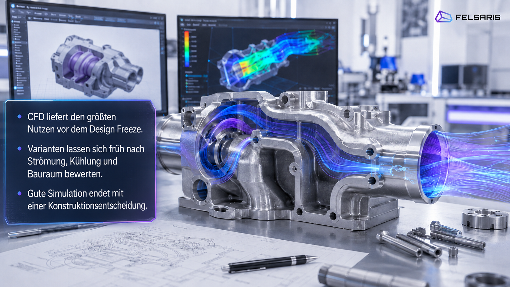
Simulation has its greatest influence on design while geometry, interfaces and system architecture are still open to change. During the concept phase, different flow paths, cooling concepts, cross-sections and component layouts can be compared. The findings can then feed directly into the next CAD iteration.
The design freeze is a project-specific approval milestone after which changes to geometry and interfaces are subject to tighter change control. CFD continues to provide value after this point through engineering verification, root-cause analysis and validation. However, the remaining design space is usually smaller.
An effective product development process therefore integrates design engineering and simulation from the concept and variant phases onwards. Shared target quantities, consistent boundary conditions and short decision loops provide the foundation. Good simulation ends with a design decision, a clearly identified technical risk or a targeted validation step.
The Design Freeze Is a Decision Point in the Development Process
The meaning of design freeze varies between companies and projects. It may refer to CAD approval, the definition of key system interfaces, a specified design maturity level or a milestone before tooling and procurement begin.
For simulation-led product development, the remaining degree of design freedom is the decisive factor. Before the design freeze, it is often still possible to modify fundamental features such as:
- flow paths and duct routing
- cross-sections and branches
- inlet and outlet positions
- component layouts
- cooling circuit architectures
- packaging arrangements
- material and wall-thickness concepts
- assembly and joining interfaces
As design maturity increases, a change can affect more areas that have already been agreed. These may include drawings, bills of materials, supplier components, manufacturing concepts, assembly processes or tests that have already been completed. The extent and impact depend on the specific product and project structure.
How the Role of Simulation Changes After the Design Freeze
Before the design freeze, simulation can compare fundamentally different concepts. After the freeze, the focus often shifts towards engineering verification and root-cause analysis.
Typical late-stage simulation tasks include:
- demonstrating specified flow or thermal targets
- identifying local weaknesses
- investigating discrepancies between tests and models
- assessing limited corrective design variants
- quantifying functional margins
- providing pressure and temperature loads for downstream analyses
- preparing validation and approval activities
- building models for the next product generation
Simulation therefore remains valuable. The development status simply imposes tighter limits on the scope of possible design changes.
Why Early Simulation Improves Design Decisions
Technical products are rarely developed against a single target. A fluid-flow component may require low pressure loss while also providing uniform distribution, limited local flow velocities, compact dimensions and a geometry that can be manufactured economically.
Cooling systems involve similar trade-offs. A geometry with high local heat transfer may also create greater hydraulic resistance. Increasing the volume flow rate can reduce temperatures while raising the required pump or fan power. A highly branched channel structure may improve temperature distribution while making manufacturing, cleaning or deaeration more difficult.
CFD can provide quantities such as:
- static pressure loss and total pressure loss
- mass flow rate and mass flow distribution
- local velocities
- recirculation zones and stagnant regions
- flow uniformity
- maximum and mean temperatures
- temperature spread
- heat flow and heat flux
- fluid-induced forces and moments
- sensitivities to operating conditions
Design engineering, manufacturing, procurement and systems engineering add further constraints, including packaging, materials, wall thicknesses, joining processes, accessibility, mass and cost assumptions.
Simulation therefore extends the design assessment by providing flow and thermal quantities that are often difficult to derive reliably from geometry alone. The final decision brings together the full set of engineering and commercial requirements.
Felsaris combines these activities through CAD design and simulation-led product development.
Variant Ranking and Absolute Performance Assessment Serve Different Purposes
During the early concept phase, the primary objective is often a relative comparison. Typical questions include:
- Which channel geometry produces the most uniform mass flow distribution?
- Which inlet position reduces local recirculation?
- Which variant limits the maximum component temperature?
- Which geometry offers the best balance between heat transfer and pressure loss?
Simplified models can provide a sound basis for variant ranking when the comparison conditions remain consistent:
- identical system boundaries
- comparable mesh criteria
- consistent boundary-condition logic
- uniform evaluation surfaces
- identical definitions of target quantities
- adequate numerical stability
- comparable physical models
As design maturity increases, the requirements for absolute values, sensitivity studies and correlation with measurement data typically become more demanding. A simplified model may distinguish between early variants sufficiently well while still requiring further detail before it can support a later approval decision.
The ranking should be reassessed if a variant introduces a fundamentally different physical regime. Examples include pronounced flow separation, strong unsteadiness, phase change, cavitation or significantly different heat-transfer conditions.
Design Engineering and Simulation Need a Shared Decision Framework
The Engineering Question Comes First
The choice of software, turbulence model and mesh size follows from the engineering task. Before a simulation model is built, design and simulation teams should jointly establish:
- Which design decision is the model intended to support?
- Which target quantity determines whether the function is achieved?
- Which other target quantities may change?
- Which operating conditions are relevant?
- Which boundary conditions are known?
- Which input data carry significant uncertainty?
- Which geometry parameters may be changed?
- Which interfaces must remain fixed?
- Which quantities will subsequently be measured?
- Which statement is required for the next approval milestone?
These questions form the basis of a shared target and decision matrix.
| Design Question | Adjustable Parameter | Target Quantity | Constraint | Suitable Method |
|---|---|---|---|---|
| Define a duct cross-section | Width, height, routing | Pressure loss, flow uniformity | Packaging, manufacturing | 3D CFD |
| Select a cooling system architecture | Pumps, circuits, valves | Temperatures across the load profile | Energy demand | 0D/1D system simulation |
| Design a cold plate | Channel geometry, material | Maximum temperature, temperature spread | Pressure loss, manufacturing | CHT |
| Assess numerous geometry variants | Parametric CAD dimensions | Multiple target quantities | Permissible design space | DoE, CFD, optional surrogate model |
The appropriate model fidelity depends on the specific decision. A system simulation addresses different questions from a spatially resolved 3D CFD model.
For guidance on model scope: When is CFD simulation worthwhile?
Defining the Design Space Together
The design space describes which variants are technically permissible. It may include:
- adjustable geometry parameters
- permissible parameter ranges
- relevant operating points
- fixed interfaces
- packaging limits
- engineering target quantities
- hard constraints
- potential manufacturing processes
- known uncertainties and tolerances
This approach follows established systems engineering principles. A trade study should document its objectives, constraints, data sources, modelling methods, uncertainties, sensitivities and selection criteria. This keeps the resulting decision traceable at a later stage.[1]
When several target quantities are involved, a Pareto analysis provides a map of the engineering trade-offs. One variant may perform particularly well in terms of pressure loss, while another may provide a more uniform temperature distribution. The final engineering choice depends on the weighting of the objectives and the project-specific constraints.
Design of experiments, or DoE, can structure the selection of variants to be simulated. Design space exploration combines iterative design with computational assessment. It is used to investigate several technically viable alternatives and progressively narrow the solution space.[2]
For large parametric design spaces, surrogate models may also be suitable. Their predictive capability is limited to the parameter range covered by the training and validation data. Promising candidates should therefore be checked using an appropriate higher-fidelity simulation or measurement.
CAD Variants Must Remain Technically Comparable
A variant study requires a traceable connection between the CAD model and each simulation case. Every calculated case should be clearly assigned to:
- a CAD version
- a set of geometry parameters
- a computational domain
- a mesh version
- a physical model
- boundary conditions
- material data
- evaluation definitions
- solver and software versions
- a result status
- the resulting engineering decision
Parametric CAD models, simulation templates and automated geometry re-import can accelerate the process. However, topology changes may invalidate the assignment of boundary conditions, mesh controls and evaluation surfaces. Every automated workflow therefore requires technical quality gates.
Suitable checks include:
- Is the geometry closed and physically plausible?
- Has the computational domain been generated correctly?
- Have surfaces and volumes been assigned correctly?
- Does the mesh meet the project-specific quality criteria?
- Are the mass and energy balances plausible?
- Have the decision-relevant target quantities stabilised?
- Are the evaluation surfaces comparable across all variants?
- Has the complete results dataset been version-controlled?
A Typical Development Process from Concept to Validation
Integrated product development connects CAD and simulation across several maturity levels.
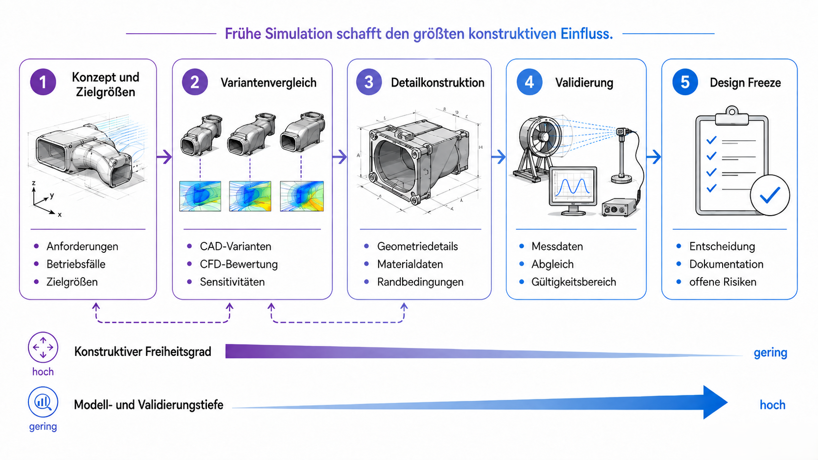
| Phase | Engineering Work | Typical Output |
|---|---|---|
| Concept and requirements | Define operating cases, system boundaries, target quantities, boundary conditions and constraints | Requirements list, simulation plan, initial design space |
| Variant comparison | Compare parametric geometries and simplified models consistently | Variant ranking, sensitivities, open risks |
| Detailed design | Add material, contact, tolerance and geometry details | Preferred design with known margins |
| Prototype and validation | Implement the measurement plan and compare target quantities | Established validity range, updated model |
| Design freeze | Document the selected variant, assumptions, risks and validation status | Traceable decision package |
Phase 1: Concept and Engineering Question
Complete detailed geometry is not required for many early decisions. Simplified models can already investigate fundamental relationships such as:
- basic flow paths
- cross-sectional ratios
- inlet and outlet concepts
- component layouts
- circuit architectures
- coolant distribution
- critical operating conditions
A concept-stage simulation includes only the details required for the current architecture decision. Small radii, screws, chamfers or manufacturing details may initially be omitted if their influence on the target quantity is plausibly limited.
Phase 2: Variant Comparison and Joint Iteration
The simulation loop should be directly connected to CAD development:
- formulate an engineering hypothesis
- modify the geometry parameters
- calculate the variants under comparable conditions
- evaluate the target quantities and physical causes
- derive the design consequence
- define the next variant or decision
A simulation report documents the results. Actual development progress comes from the resulting design change or approval decision.
Root-cause analysis is particularly valuable. A lower pressure loss alone does not explain why one variant performs better. Flow fields, pressure distributions and local losses may reveal whether bends, abrupt cross-sectional changes, flow separation or unfavourable distribution regions are responsible. These findings can then be translated into a specific geometry change.
Phase 3: Detailed Design and Higher-Fidelity Modelling
Once a concept has been selected, the level of detail increases. Depending on the engineering question, the following properties may become relevant:
- actual wall thicknesses
- heat conduction in solids
- thermal contact resistances
- seals and gaps
- actual surface roughness
- manifold and collector geometries
- manufacturing tolerances
- component maps
- transient loads
- control strategies
- additional operating points
- pressure and temperature loads for FEA
Model fidelity remains linked to the decision being made. A local geometry assessment requires different details from the evaluation of a complete load profile.
Phase 4: Validation and Model Updating
Validation assesses whether a model represents the relevant real-world physics sufficiently well for a defined purpose. Four terms should be distinguished:
- Verification: Has the numerical model been solved with appropriate numerical and methodological rigour?
- Calibration: Have model parameters been adjusted using known data?
- Correlation: How closely do simulation and measurement agree for the selected quantities?
- Validation: Is the level of agreement sufficient for the intended use?
NASA-STD-7009B requires a traceable treatment of requirements, acceptance criteria, verification, validation, sensitivities and uncertainties for models and simulations.[3] ASME V&V 20 applies these principles to CFD and heat transfer. The standard considers accuracy for defined validation variables at specified validation points and incorporates uncertainties from both simulation and experiment.[4]
Measurement data require documented boundary conditions, sensor positions, signal processing methods and uncertainties. Low residuals or a stable solver run alone do not demonstrate sufficient agreement with the real application.
A precise statement might read: The model was validated for pressure loss within a defined mass flow range against specified measurement data. This wording identifies both the target quantity and the validity range.
Engineering Example: Developing a Cooling System
A cooling system or fluid-flow component must reject a specified heat load. Packaging, connection positions, manufacturing processes and the available pump or fan operating points constrain the solution space.
Potential Design Parameters
The following features may be varied during the concept phase:
- number and arrangement of channels
- channel cross-sections
- branching angles
- inlet and outlet positions
- manifold geometries
- bends and flow-guiding structures
- material and wall thickness
- thermal contact areas
- heat exchanger position
- pump or fan operating curve
Relevant Assessment Quantities
| Category | Assessment Quantities |
|---|---|
| Thermal | Maximum temperature, temperature spread, heat flow, local hot spots |
| Hydraulic | Pressure loss, mass flow rate, distribution across parallel paths |
| Energy | Pump or fan power, system energy demand |
| Design | Packaging, mass, interfaces, accessibility |
| Manufacturing | Channel manufacture, wall thicknesses, joining processes, tolerances |
| Robustness | Behaviour at other operating points or under variation |
| Validation | Measurement points, acceptance criteria, validity range |
Conjugate heat transfer, or CHT, calculates fluid flow and heat conduction in the solid as a coupled problem. The component temperature results from the complete thermal path: the heat source, material, contact resistances, geometry, coolant flow and external boundary conditions.
A pure flow simulation can assess coolant distribution and hydraulic resistance. Reliable component temperature predictions may require additional solid and contact models.
The Engineering Selection Emerges from the Trade-Off
A representative variant comparison might produce the following findings:
- Variant A has low pressure loss but a greater temperature spread.
- Variant B distributes coolant more uniformly but requires greater pump power.
- Variant C provides favourable thermal performance but places greater demands on manufacturing and joining processes.
Simulation makes these differences quantitatively visible. The final selection considers function, packaging, energy demand, manufacturability, cost assumptions and validation risk.
Selecting the Right Model Fidelity for the Design Decision
| Model Level | Suitable For | Typical Target Quantities | Limitation |
|---|---|---|---|
| Hand calculation or 0D model | Order-of-magnitude estimates, heat and mass balances | Power, mean temperature, volume flow rate | No local distribution |
| 1D system simulation | Circuits, maps, dynamics, controls and load profiles | Pressures, temperatures and mass flow rates across operating conditions | Local hot spots are simplified |
| 3D CFD | Local flow, pressure loss, distribution and flow separation | Velocity, pressure, distribution, forces | Greater modelling and computational effort |
| CHT | Coupled fluid and solid thermal behaviour | Component temperatures, heat flow, temperature spread | Requires suitable material, contact and heat-load data |
| FEA or structural model | Mechanical loading due to pressure and temperature | Stress, deformation, life indicators | Requires material models and suitable load transfer |
| Surrogate or reduced-order model | Numerous similar evaluations within a defined design space | Rapid prediction of selected target quantities | Limited training and validation domain |
1D and system models are particularly suitable for circuits, control strategies and the transient behaviour of the overall system. 3D CFD resolves local geometry effects spatially. CHT adds the solid component and its heat conduction. Structural models evaluate the mechanical response to the calculated loads.
A surrogate model can accelerate repeated evaluations if the design space, training data and validation limits are clearly defined.
The Felsaris core competencies combine these different modelling levels with CAD design, flow analysis and technical product development.
What Late-Stage Simulation Can Still Deliver
Late-stage simulation remains an important part of technical development. It can:
- investigate discrepancies observed during testing
- reveal local flow disturbances
- identify thermal bottlenecks
- compare corrective design variants
- support the physical interpretation of measurement data
- provide loads for downstream analyses
- assess functional margins
- establish validated models for future projects
The main difference lies in the available room for change. A fundamental modification to the flow concept may form part of an early variant study. After several approval stages, additional dependencies usually have to be considered.
Late changes may affect existing drawings, bills of materials, components, assembly procedures, tests or procurement decisions. The actual effort depends on the product, manufacturing process, supply chain and project status.
How Teams Can Organise Collaboration Between Design and Simulation
A Shared Technical Project Kick-Off
An integrated project kick-off should establish:
- the engineering decision to be supported
- target quantities and constraints
- relevant operating cases
- system boundaries
- available data sources
- significant uncertainties
- responsibility for CAD
- responsibility for simulation
- responsibility for the decision
- the validation strategy
- the maturity level required at the decision milestone
This gives every simulation a clear purpose. The design team understands which output quantities are required. The simulation team understands which geometry changes are permissible and which downstream decisions depend on the results.
Short, Documented Decision Loops
A practical workflow consists of six steps:
- release the CAD version
- confirm the simulation assumptions
- calculate the variant
- review target quantities and physical causes jointly
- document the decision and open risks
- release the next CAD modification
The loops should match the development pace of the project. An early concept decision may require only a small number of target quantities, while a later approval usually requires more comprehensive documentation.
Version Control and Traceability
Every assessed case should preserve the link between inputs, model and decision. This includes the CAD version, mesh, boundary conditions, material data, evaluation method, result status and open assumptions.
Automation can support repeatable steps. Geometry checks, boundary-condition assignments, mesh quality, convergence assessment and results extraction remain part of technical quality assurance.
Clear Technical Accountability
A shared decision framework requires clearly defined responsibilities:
- Design engineering is responsible for geometry, interfaces and manufacturability.
- Simulation is responsible for model assumptions, numerical quality and the limits of interpretation.
- Systems or project leads bring the competing objectives together.
- Approval and overall technical responsibility follow the governance of the individual project.
This role structure creates a shared working basis while retaining discipline-specific accountability.
Good Simulation Ends with a Design Decision
A CFD result image shows calculated flow, pressure or temperature fields. Its engineering value comes from the interpretation and the action derived from it.
A simulation run may lead to several outcomes:
- modify the geometry
- reject a variant
- narrow the parameter range
- verify an operating point
- plan an additional measurement
- review a model assumption
- build a higher-fidelity model
- release the design for the next maturity level
Good simulation ends with a design decision, a clearly identified risk or a targeted next validation step.
Felsaris supports these development processes through CAD design, 3D CFD, flow and heat transfer analysis, system-level assessment and project-specific validation logic. The most useful inputs for an initial technical assessment are the project objective, system boundary, available geometry, relevant operating conditions and existing measurement data.
Selected applications are presented in the Felsaris case studies.
Frequently Asked Questions About Design and Simulation Before the Design Freeze
When Should CFD Begin in Product Development?
CFD can begin as soon as a specific engineering question, initial geometry concepts and relevant operating conditions are available. Fully detailed CAD geometry is often unnecessary for early architecture and variant decisions. The required model scope should be derived from the decision the simulation is intended to support.
Can CFD Be Used with Simplified CAD Geometry?
Yes, provided the simplified geometry still represents the relevant flow and heat-transfer effects adequately. Interfaces, cross-sections, flow paths, heat sources and system boundaries must remain representative. The effect of removed details should be assessed and documented.
Which Decisions Can Simulation Support Before the Design Freeze?
Simulation can support the selection of flow paths, cooling concepts, cross-sections, manifold geometries, inlet positions and component layouts. The assessment is based on defined target quantities such as pressure loss, mass flow distribution, maximum temperature or heat flow. Manufacturability, cost and mechanical integrity require additional specialist assessments and input data.
How Should Design Engineering and Simulation Work Together?
Both disciplines need shared target quantities, a defined design space and short, documented variant loops. Every simulation case should be linked to an unambiguous CAD version. The findings should then lead to a design change, a decision or a further investigation.
What Is the Difference Between Variant Comparison and Validation?
A variant comparison ranks different designs relative to one another. Validation assesses model quality against real data for a defined target quantity and operating range. A consistent variant ranking does not constitute general validation of the model.
Does Early CFD Eliminate the Need for Prototypes?
CFD can narrow the range of variants and focus physical testing on the remaining engineering risks. The required scope of prototyping and validation depends on function, model uncertainty, safety requirements and the approval process.
When Is 1D Simulation Sufficient, and When Is 3D CFD Required?
1D models are suitable for circuits, system architecture, component maps, control strategies and transient operating conditions. 3D CFD becomes relevant when local geometry effects, flow distribution, separation or hot spots determine the decision. The two modelling levels can also be coupled.
Is Simulation Still Useful After the Design Freeze?
Yes. Simulation continues to support engineering verification, root-cause analysis, the interpretation of measurement data and the assessment of limited design changes. The available design space is often smaller because more interfaces, approvals and procurement decisions must be taken into account.
Technical Sources
[3] NASA-STD-7009B: Standard for Models and Simulations. NASA, issued 5 March 2024.